Monday, 2 September 2019

Amiga to BeagleBone Black


Amiga 500 Zorro to BeagleBone Black

My Ramblings...

These are my thoughts on how to get an interface from an Amiga500 to a Beaglebone. The diagrams may not work at all, but they help me visualise the problems of interfacing. 


There are many challenges, the BBB has got limited PRU high speed IO lines - so I have opted to multiplex them. Additionally, BBB runs at 3v3 - and the Amiga is 5V; there will be many level converters but I am keeping it brief for now.

The Multiplex - Address Lines

For the one port, bytes are sampled in 3 clocks. This is typically with the ADDRESS SELECT line becomes VALID. This will signal the PRU to sample the values and check for an address in the most significant byte. 
I am trying to avoid a CPLD, but if needed I will offload the Address decode to one if I cant get it to run fast enough.

I should be able to latch all the addresses within 60nSeconds using just the PRU

Amiga 500 Main Clock (PAL variety)


Prototyping Board (Zorro connector) - with BBB attached

 I managed to source a connector - and soldered to a Prototyping board. Bending the pins on the connector to make it right angled was a tiresome task.. and getting all the pins though the holes was a challenge when all the legs have a mind of their own


The DATA bus buffers

As the BBB does not have fast switching of INPUT and OUTPUT, a multiplex was chosen so that all INPUTS are on one set of pins.. and outputs on another.

All reads are muxed to PRU0 and Writes are to PRU1. 74HCT573 latches are used to put lock the data on the bus in preparation for reading from the master - and after read the pins are set to high impedance as to not mess with the data in the case of a read. 


  Address and Some MUXing action..

Amiga timing 

From the charts, it looks like 300nSeconds is average... but 200nSeconds was seen on my scope? Either way.. I was aiming for 200nSeconds as a maximum


Friday, 30 August 2019

BeagleBone Black PRU

BeagleBone Black - Adventures with PRU

 Part of 'How fast can you make a GPIO toggle, I have now just done a torture GPIO toggle on BeagleBone just to see how fast it can run.

From the looks... it may just do the trick! - hopefully emulate a RAM chip and peripherals in an Amiga!

The Setup,

From The PRU guide on Element 14 the setup is pretty straight forward main difference is you dont need to install the code composer studio as the BBB gets configured with all the PRU software. What you do need are the samples; and put them anywhere you like.

 Update the kernel - nice but not really needed
  1. sudo /opt/scripts/tools/update_kernel.sh  
  2. sudo apt update  
  3. sudo apt upgrade  
  4. sudo apt dist-upgrade 
Connect to the BBB and link the compilers and do the export.
ln -s /usr/bin/ /usr/share/ti/cgt-pru/bin
export PRU_CGT=/usr/share/ti/cgt-pru

Next to get the sample code from GIT

git clone git://git.ti.com/pru-software-support-package/pru-software-support-package.git 
Change to the directory with the examples downloaded in the previous step - and run the makefiles
cd /opt/source/pru-software-support-package/examples/am335x
make
 Once compiled, set the IO pins
sudo config-pin P9_27 output
sudo config-pin P9_27 pruout
 and then copy the firmware files to /lib/firmware on the BBB

cd /sys/class/remoteproc/remoteproc1
 echo '<firmware name>' firmware
 echo 'start' > state
*NOTE - the example in the download does not toggle P9_27 - change to 0x0020 in the sources ffor gpio.

From the small application - Toggling P9_27; there is 25nSecond for one pulse. Loaded in to the PRU and voila!

#include <stdint.h>
#include <pru_cfg.h>
#include "resource_table_empty.h"

volatile register uint32_t __R30;
volatile register uint32_t __R31;

void main(void)
{
        volatile uint32_t gpio;

        /* Clear SYSCFG[STANDBY_INIT] to enable OCP master port */
        CT_CFG.SYSCFG_bit.STANDBY_INIT = 0;

        /* Toggle GPO pins TODO: Figure out which to use */
        gpio = 0x0020;
        while (1) {
                __R30 ^= gpio;
//              __delay_cycles(100000000);
        }
}
 
From the FFT trace - there is all sorts of frequencies in there.. the harmonics are awesome!


Update:

Even without using high speed PRU GPIO pins, the access to normal pins from the PRU is still quite a respectable 80nSeconds. (ignore the yellow trace, its connected to the high speed line which is doing nothing)


Avaliable Pins on a BeagleBone Black


STM32F4 Interrupt latency - how fast can it go

STM32F4 - Interrupt latency

Following on from the ESP32, (ESP32 Interrupt Latency) I had a STM32F401RE Neucleo board lying about.. this was the next test bed for how fast can an interrupt go; and how fast can it manupulate a GPIO. Using OpenSTM32 development package and in C (no assembler yet)

First try - Using an Interrupt

My first experiment was with INTERRUPT routines. This shows how long it takes for the STM32F4 to act on an ISR  - 3uSeconds from the trace.


The YELLOW trace is the GPIO line dropping, the CYAN trace is another pin being cleared within the ISR function. I have a target of 100nSec to reach; I think that target is a bit much for this CPU


How fast can it actually toggle?

One thing I didn't look at was how fast the pin can be toggled.


Hmm... ~300nSecond for one pulse- and that is a while(1) set clear set clear loop using register access.  If the chip cant toggle at a fast pace, I dont think I have any hope reading a GPIO in a busy-wait loop.

Conclusion

The STM32F4 CPU isnt quick enough to interface directly to an 8Mhz bus on the Amiga. 

NEXT

The BeagleBone PRU speed ... https://gruhouse.blogspot.com/2019/08/beaglebone-black-adventures-with-pru-of.html


Monday, 22 April 2019

ESP32 Interrupt latency - its dismal

ESP32 Interrupt Latency

Thinking of a simple way of interfacing to my Amiga without using glue logic, I looked at the ESP32 as a candidate. 

The aim was to replace the realtime clock using an NTP one - one inside the ESP32. The Amiga has a 4bit address and a 4bit data bus for for clock connected directly to the CPU - so that was nice.

As the clock is directly on the bus, the speed of the ESP32 is critical - and more importantly - how quick can the ESP32 get an interrupt and store the address latch and then serve the data. 

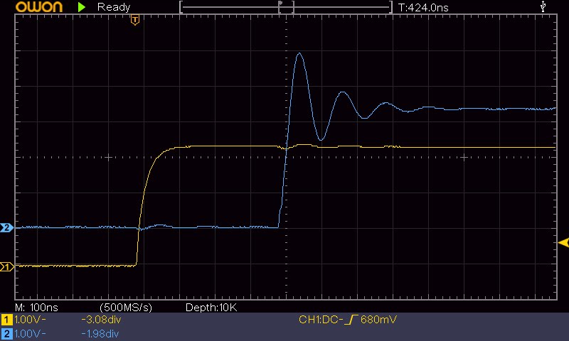
RAM speeds are 150nS - so that was the target; for a modern 200Mhz dual core xtensa it should be no trouble.


A small program that toggles an IO pin at 1Hz and a second output being triggered within the ISR. All using the default ESP-IDF C and examples.

From the plots - The latency is HORRIBLE! 2.5uS is what it takes to register the interrupt. Even with fudge of the code setting the GPIO inside the ISR.

Yellow trace is 1Hz toggle - Blue trace is the output being triggered within the ISR


Conclusion -

Without heavy lifting of writing code in Assembler, the ESP32 cannot service interrupts quickly! 


** UPDATE **

Removed the ISR functions and replaced with a BUSY-WAIT loop.. looks alot better but no cigar -  but its a HUGE improvement!


 Total time changed to 424nS


**UPDATE**

I removed the C function gpio_get_level() and replaced with a direct register write

GPIO.out_w1ts = (1 << ISR_OUTPUT);


Down to 256nS for a trigger... better.. Now to shave 200nS off!

Thursday, 19 July 2018

HF Noise Generator

HF Noise Generator

One of the tools needed for building a HF receiver is a noise generator. I can go in to the physics of revered biasing transistor components - but I just wont. 

The usage of the noise generator is to test Band Filters - and to see how well the perform to white noise. 

I built a quick one based on KB8OJH's practical examples and it works a treat. The dead-bug style construction.


The Spectrum analyser shows some good results.

From 1Mhz to 30Mhz its not quite flat, but it has lots of frequency components in it.


from 1Mhz to 200Mhz, there is a large drop from 56Mhz onwards, but I don't care too much about that side.


For a sim

Sunday, 24 June 2018

Adventures in Antennas (The Random Wire)

Adventures with Antennas

The Random wire

From my previous post, I was experimenting in a random wire antenna. The first thing I needed was a 9:1 UnUn to get the antenna impedances to a range the autotuner can handle. I followed the blog entry Magnetic Longwire Balun which worked out very well. 


The main ingredient was 10.6Mtrs of wire,a 6M telescoping fiberglass pole and some bungee straps to fix the pole to the fence-post.

Right next to the antenna is a metal fence, which I dont like! so I opted to elevate the base of the antenna to the top of the fence post. It was convenient as the counterpoise was the actual fence. 

You will notice that the black pole is leaning forward as I wanted the the last 4 meters to be a pseudo-V shape.


The antenna analyser shows that the antenna being quite poor in the frequencies I want to use; which is good.

Surprisingly it show that it will work okay from 18Mhz.. well barely!

The performance

Connecting to the LDG Z-11 Pro tuner, it had no problem of reducing the SWR to 1.5 and below. 

Firing up WSPR and running the radio at a massive 2 watts - I was impressed with the spots; considering it was made in 10 minutes at my dismal skill level.


The random wire will not win any awesome propagation awards, but as a compromise antenna it does the trick.

Adventures with Antennas - Dipole [Previous]


Adventures with Antennas (the Dipole)

Adventures with Antennas (the Dipole)

(playing with wires)

As all the HF radio equipment I use is QRP, I tinkered with the usual inverted V configuration. Mine is constructed using scaffolding poles, aluminum sections and lots of concrete with a pivot base. Just cos it pivots, doesn't mean it is easy to lower and raise. 


There are 2 antennas in the picture, the inverted V is the silver one. The apex is 10mtrs and it has a 20M and 40M HF dipole elements attached.

Its pretty much tuned for the 2 bands I want to use, but the LDG Z-11 Pro autotuner I use will make a match of a wet piece of string. 

The other antenna shown is a random wire experiment as it was the first time I have ventured in to the world of the UnUn.


But first, the Dipole; from the antenna analyser, its tuned for the frequencies I want. -perfect-


showing the HF spectrum from the analyser, the two resonant frequencies where tbe impedance is 50ohms or there about is shown.